9b. Aeroworks Extra 260 Build Log – DLE-20cc Gasoline Engine Conversion (Updated 8/14/2016)
Scroll down to read the DLE-20 20cc Gasoline Engine Conversion
12/29/2008 – I placed the order with Chuck at Aeroworks on Monday 12/15/2008 and my order was shipped that day! UPS had scheduled the delivery for Friday the 19th, however, due to the holiday crush UPS was unable to make the deliver until Monday the 22nd.
The box arrived in good shape and upon opening I found the contents to be well packaged and with no visible damage.

The AW Extra 260 arrived well packaged and with no damage
12/30/2008 – Other projects keep cropping up which are keeping me away from the Extra. More posts later.
1/27/2009 – Just been to busy to get this build going.
2/7/2009 – Inspected the contents of the box for damaged parts and then matched the contents with the materials list. Not finding any issues, I’m finally ready for the first build step. (Update – On further inspection, I did find some missing parts. The small bag containing the wing attaching hardware came up missing. It is usually tucked inside the wing tube but mine wasn’t there. I called Chuck at AW and he is sending me a replacement at no charge)
Starting with the wing halves, I used my sealing iron and went over all seams and overlaps. Even though the covering on the wings looked tight, it is a good idea to run an iron over it. A heat gun was needed for a few wrinkles.

Preparing wing for covering tightening and re-shrinking

Ironing seams and overlaps to insure a tight seal

Removing wrinkles
Next, I attached the ailerons using the supplied CA hinges and Mercury Adhesives thin CA. Usually in the Aeroworks QB kits, the control surfaces would be securely mounted.
However, the .60 – .90 size kits are supplied with typical CA hinges that are mounted but not secured, this allows the builder the option to use a different type of hinge.
The CA hinges are made of a very high quality material and are pre-cut with rounded corners and pin holes. There is a channel cut from the center of the hinge which allows for better CA wicking.
The pin holes aid in the alignment of the hinges so that an equal amount of hinge material is in both surfaces. After pinning and aligning the aileron, the pins are removed and the two surfaces are pressed together so that as little gap as possible is showing before gluing.

The supplied CA hinges are of very high quality

Use T-pins to align the hinges when mounting the control surface
Mounting the Hitec HS-645MG servos is straight forward. The covering over the pre-cut servo wells was removed at the factory. A draw string to fish the servo wires through the wings is preinstalled.
I drilled 1/16th servo mounting holes and cut the threads with #2 x 9/16 servo mounting screws from RTL Fasteners. I then applied thin CA to harden the screw holes.
Note– The instructions on page 11, step 7, indicate that the servo arms should be pointing towards the wing tip. However, I find that installing the arms in this manor would cause a misalignment of the control horn. So I installed the servo arm pointing towards the wing root. This is not an issue, just noting the discrepancy.

Use the installed string to fish the servo wire through the wing

Drilling 1/16th servo mounting holes

After cutting the threads apply thin CA to harden the screw holes

I use 5/64 hex head servo mounting screws (RTL Fasteners #583)
Next the control horns are mounted using the predrilled holes and supplied hardware. These control horns are heavy duty and should hold up just fine.

Completed servo and control horn installation
2/12/2009 – Got the engine today from Tower!

OS 75AX ABL – 2.4 hp @ 15,000 rpm
2/14/2009 – Installed the horizontal stab and elevator. I applied 30 minute epoxy to the factory exposed wood on both sides of the stab, inserted the elevator then the stab and aligned accordingly and let it set.
Be sure to get the installation order correct. The elevator is a one piece design and must be inserted into the fuse before the stab is affixed.
When the epoxy cured, I CA’d the elevator to the stab using the same hinge pining method as the ailerons.

Insert elevator before securing the horizontal stab


After epoxy has cured CA elevator to horizontal stab
I installed the Hitec HS-645MG elevator servo using the same method as the aileron servos.
However, this installation required a 12″ extension and an Aeroworks safety connector clip. Since the servo lead runs the length of the rear portion of the fuse, I used 1/4″ red nylon expandable braided sleeving, from Cable Organizer.com, to protect the lead from chaffing caused by repetitive movement and vibration.

Elevator servo and control horn installed

Elevator servo, 12

1/4
Next, I mounted the rudder to the factory installed vertical stabilizer using the same method as the elevator.

Mounting the rudder
2/15/2009– Now it’s time to install the Hitec HS-645MG rudder servo and Pull-Pull cables.

Pull-Pull cable assembly parts
I attached the rudder control horns and mounted the rudder servo using the same techniques as previously described.
I then ran a Pull-Pull cable through each of the pre-installed cable tubes located near the end of the fuse and attached each one to a coupler. Both couplers were then mounted to the rudder servo arm.

Completed cable coupler

Rudder servo and mounted Pull-Pull cable couplers
I attached couplers to the other ends of the Pull-Pull cables and mounted them to the rudder control horns.

Pull-Pull couples mounted to rudder control horns
2/16/2009 – After the rudder cables were installed, it’s time for the main landing gear assembly.
I attached the axles and wheels then the wheel pants. One note, be sure to install the axles with the flat sides of the axle back plate perpendicular to the gear strut. This is required for the wheel pants to fit flush against the gear strut.
Use blue Loctite removable thread locker on all bolts and screws.

Main gear installed
On to the tail wheel. After attaching the rudder tiller steering arm and tail wheel, I attached the steering springs.
The documentation is light in covering this step and I had to look else where for some direction. I found the needed information in the Aeroworks .90 – 1.20 Yak 54 assembly manual. Page 30 describes the mounting procedure.
Of note, the springs are delicate and I managed to break one. I called Chuck at Aeroworks and he is mailing a set out to me. The cost was $6.95, so be careful when twisting the spring ends closed.

Mounted tiller steering arm and tail wheel

Attaching the rudder steering springs
Now we’re making progress. On to the engine installation.
Using the supplied engine mount and hardware I attached the mount to the firewall using the predrilled mounting holes. Blind nuts are factory installed in the firewall.
Setting the engine between the mount rails, I set the distance of the engine thrust washer 4 3/4″ away from the firewall as recommended.
Using a mechanical pencil with plenty of lead showing, I marked the locations of the engine mounting holes onto the mount. I then drilled 1/8″ holes and secured the engine using the supplied hardware.
The next step is to mark the location of the throttle push rod guide, then remove the engine mount, drill the firewall hole for the guide tube and install the guide tube using CA.
After the guide tube is installed, I remounted the engine to the firewall using blue Loctite.
I have not secured the engine to the engine mount rails for now. I plan on removing the engine to break it in on my engine test stand.

Reinstalling engine

Engine mounted
I used a standard Futaba S3004servo for the throttle. Using the precut mounting hole I used the same procedure as previously described.
I inserted the supplied throttle push rod through the guide tube and attached one end to the carburetor arm and the other end to the throttle servo.

Futaba S3004 servo installed for throttle control

Supplied throttle guide tube, pushrod and clevis

Completed throttle installation
2/17/2009 – I assembled the fuel tank using Du-Bro medium silicone fuel tubing. The supplied fuel tubing is perfectly fine, this is just my preference.

450cc fuel tank
Make sure that when you put together the pick up line clunk, it is long enough to reach the end of the tank but does not contact the tank end. This prevents the clunk from becoming stuck and drawing air.

Make sure the clunk does not touch the end of the tank
I fully tightened down the stopper to prevent any leaks and the tank is now ready to be installed.

Installed fuel tank using supplied foam vibration pad – Plastic ties will hold the tank in place
I measured and cut to length the carburetor, muffler and fill lines. The I routed the fill line to the right side of the fuse and installed a Hanger 9 fueling dot.
I first mounted the right main wing to be sure I had the proper clearance then found an open spot on the fuse located as high as possible, drilled a 23/64 hole and used blue Loctite on the mounting nut.

Fueling dot installed and fuel lines connected
3/6/2009 – Received the engine break-in stand today. I was looking for an inexpensive option to breaking-in the engine installed on the plane. I found this one at Richmond RC for $19.99!

Vmar engine break-in stand from Richmond RC
It appears rugged enough to handle the job and I’ll find out how it performs this weekend.
4/18/2009– Finally had the chance to break-in the engine. The Vmar stand did its job.
However, I neglected to use loctite and every one of the stand nuts backed off due to vibration. I noticed this problem half-way through the first tank and stopped until I replaced the nuts. I replaced the provided nuts with nylok locking nuts and problem solved.

Vmar engine break-in stand with OS .75AX engine and 14 x 6 APC prop
Because the stand tank is small, I ran through two tanks following the OS AX engine recommended break-in procedure. One minute with the throttle fully open running four-cycle rich. Then alternating between rich four-cycle and less rich two-cycle operation every 10 seconds for the remainder of the tank.
The break-in procedure is completed by three or four two-cycle rich flights.
4/27/2009 – I remounted the engine to begin the cowl installation. A clearance cutout for the exhaust needs to be made using the supplied template material. The template is taped to the fuselage and the outline of the exhaust is traced onto the template.
The template is cut following the traced outline then overlayed onto the cowl and retraced.
Using a Dremel with a cut-off wheel attachment, I cut out the clearance hole.
Air inlet holes for cooling are also needed and the supplied template allows you to quickly trace the lines. To finish up, an access hole for the glow plug and needle valve is needed following the same technique as the exhaust cutout.

Exhaust cutout was made using the same technique used for the glow plug hole
The cowl mounting holes are pre-drilled and using the six supplied screws and rubber bonded washers allows for quick and painless mounting.

The completed cowl cutout and mounted
4/29/2009– I trimmed the Great Planes 2 1/4″ aluminum backed spinner to fit the large APC prop. The included spinner is of very good quality, but I personally like the GP aluminum backed spinners. Per the manufacturer: “The aluminum back plate holds the spinner in round which means it turns truer with less vibration”, and it looks nice! Then I mounted the JR switch harness next to the fuel dot. This finished the assembly work.

Spinner trimmed and receiver switch mounted
4/31/2009 – The main wings are attached using one bolt and two retaining clips per side. The wing tube is carbon fiber and slipped in nice and snug.

Each wing is secured in place by a bolt and two retaining clips
I installed the JR R921 receiver and A123, 6.6v, two cell, 1,100mAh battery in the recommended locations.
It’s nice having plenty of room to work with. However, using this configuration required an ounce of ballast on the tail to balance at the 2 1/4″ suggested CG location.
This can be remedied by relocating the battery pack to the rear of the fuse. I’ll work on that after the first flight.
I also installed a Spektrum Flight Log. This will allow review of the RF link between the transmitter and receiver after each flight. This information is useful to determine if adjustments are necessary to the receiver antenna positions.

Large bay easily accommodates the receiver, battery and flight log
I applied the supplied vinyl decals using the clear transfer tape. Be sure you use a wetting agent on the plane or you’ll only get one shot to get it right.

Lay the decal transfer tape over the decal and firmly press, then slowly peel the backing away from the decal

Wet the location of the decal, apply the decal, squeegee and remove the transfer tape

She
5/1/2009 – Jason took the Extra on her shakedown flight while I shot the video and the little Aeroworks flies like a champ. Unlimited vertical, hands-off knife edge, slow and predictable stalls, dead straight up lines and down lines, axial rolls and hard snaps.
Looks like the OS .75 AX with a 14 x 6 APC prop turned out to be a really good combination for this plane.

Heading for the sky
When it was my turn to fly I immediately felt connected to the plane like nothing I’ve flown before. This is my first pure aerobatic airplane and the feel of the quality and engineering of the plane along with high end electronics was immediately noticeable.
************************************************************************************
DLE-20 20cc Gasoline Engine Conversion
1/10/2011 – Stopped by the Aeroworks booth during the recent AMA Expo and saw the .60 .90 Extra 300 with the DLE20cc conversion.
I picked up the Extra 260 conversion kit and ordered the engine, fuel tank, fuel line installation kit and motor mount.
1/18/2011 – I just received the DLE-20 20cc gas engine and conversion accessories from Aeroworks.
My Extra has been a great flier for sometime now and the OS 75AX has given me no problems. I wanted to get into gasoline power but was afraid that a lot of the small gas engines would be an expensive disappointment.
When Aeroworks came out with the DLE-20 installation kit and had proven the capabilities and reliability I was ready to give it a try.
Watch a flying video of a Extra 300 with the DLE-20.

DLE-20 20cc Gasoline Engine
First order of business is to download the Hobbico version of the DLE-20 user manual. Much better!

Aeroworks Extra 260/300 60-90 DLE-20 Conversion Accessories
The conversion requires a smaller 8oz fuel tank and of course gasoline proof fuel line. The motor mount is needed as the one currently installed is drilled for the OS. I don’t expect to have to add or change any other currently installed equipment. The only other addition will be an Ignition Battery Elimination Circuit (IBEC) to power the ignition and receiver off of one battery and maybe a larger capacity A123 battery.
I’ll get into the installation kit specifics as I start the install.
1/19/2011 – On the operating table!

Slimer to Gasser transplant ready to begin
1/20/2011 – The Aeroworks DLE-20 installation kit comes with a very detailed step-by-step guide complete with photos, so there’s no need for me to detail every step.
To get started, you need to cut access holes in the motor box firewall to accommodate the rear mounted carburetor and I believe a breather hole in the top of the box. The breather hole also allows for access to the high and low speed adjustment needles. (I’ll show detailed pictures when the engine gets installed.)
Using the supplied engine mount template I marked the new motor mount holes and cut-out lines. I used my Dremel with a rotary cut-off blade to remove the marked area. A little clean up is required as it’s a tight fit and a small recess is needed to be cut out to accommodate the carburetor idle screw mount.

Cut-out lines

Cut-outs and recess for carburetor idle screw mount
Note that the instructions do not mention the need to remove the carburetor idle adjustment screw to get the carburetor to fit through the firewall hole. This is probably because it’s a no-brainier that of course it would be removed but I’m new to gas engines and didn’t know.

Throttle idle screw needs to be removed

Idle screw will not be used in final installation
1/21/2011 – In addition to the idle screw modification, there is a throttle return spring that needs to be unhooked or clipped, vestiges from the leaf-blower DNA these engines come from. Make sure that there is no tension on the throttle.
Note: After removing the throttle spring hook make sure there is no binding of the throttle valve, especially near the closed position. If not completely unhooked the spring might bind near the closed position. I induced this issue and had to go back to work on that spring (from the underside of the throttle arm) to make sure it was completely unhooked.
When I first set up the throttle servo throw I used the slight binding of the push rod to indicate the fully closed position. In reality I still had a bit more throw that you could only see when manually operating the throttle valve.

A close-up of the spring hook that needs to be clipped
When installing the engine, you may need to trim the corner of the motor mount to provide clearance for the throttle arm.

Throttle arm makes slight contact with the motor mount
1/21/2011 – Starting on the fuel tank. With gas fuel line, the brass tubes require barbs which help keep the tubing attached as the gas tubing will expand over time and will slip. The barbs only need to be soldered onto the ends of the pick-up line. The vent line does not require barbs, plastic ties will be sufficient.
When soldering on the barbs, make sure they face the correct direction and that you don’t solder on both barbs before inserting the tube into the stopper and stopper mounts. Don’t worry, if you happen to solder both bards before inserting the tube, a little heat will allow you to remove one end. 🙂

Make sure the barbs are facing in the correct direction
This was my first attempt at soldering on barbs and found that a solder iron was taking way to long. I pulled out my butane torch which quickly and efficiently did the job.

Perfect tool for soldering on barbs
1/23/2011 – Relocated the throttle servo. Mounted the installation kit supplied throttle servo tray and installed the servo.

Relocated throttle servo
Next I installed the choke bell crank assembly. The newer version of the kits now have the assembly preassembled. Another appreciated Aeroworks touch.
I took some time to pre-fit the linkages and understand the bell crank orientation. I configured the choke to be in the open position when you pull down on the choke pushrod. Not sure if there is a right or wrong way for this.

Choke bell crank assembly
1/24/2011 – Finished mounting the engine. The guide calls for the thrust washer distance of 4 3/4″ from the firewall, but after carefully triple checking and using my spinner back plate, I found that I needed to be 4 7/8th from the firewall. I need to trim a bit of the bottom of the cowl to provide clearance for the muffler tip.

Engine mounted
I’m waiting for the arrival of a Tech-Aero Ignition Battery Elimination Circuit (IBEC) to manage remote engine kill, ignition switch, ignition voltage regulation, RF filtering, and allow for the use a single battery for the receiver and ignition.

Tech-Aero IBEC
1/30/2011 – Having a problem setting up the throttle in the relocated servo position. There’s not a lot of room for servo arm travel and I’m hitting the wing tube tunnel at closed position and then over rotate the linkage (the plastic keeper on the pushrod hit the servo body) for wide open.
Resolved the issue by re-relocating the throttle servo so that I now have plenty of throw travel to work with. I made a servo mounting tray from thin ply and I needed a bit longer pushrod.

Re-relocated the throttle servo
Next will be the fuel tank mounting, ignition, IBEC, and battery placement.
2/4/2011 – Conversion is complete. Interesting that the CG balance is now more neutral.
Engine break-in and maiden flight planned for tomorrow. I’ll be using a Xoar 16 x 6 prop using regular unleaded gasoline mixed 32:1 with Lawn Boy 2-Cycle oil.

A123 2,300 mAh 6.6v LiFe ignition and receiver battery

IBEC located in the bottom left of picture

Ignition mounted on engine box
2/5/2011 – Broke-in the engine and flew the maiden this morning. Gave everything the once-over, fueled up, opened the low speed needle 1 1/2 turns, the high speed needle 2 turns, closed the choke, turned on the ignition, gave it about 10 flips till she popped, opened the choke, 3 flips and she started. No drama, no “why’s it doing that?”
Let it warmed up, leaned it a bit for idle, leaned it a bit on the high end, ran about a tank full. Double checked that everything was still tightened down, filled it up and flew it. Flew like a dream, as they say. No problems, nothing but good flying.

On the table getting the once-over

All ready to go
2/20/2011 – So far I’ve been able to put 20, 12 minute flights on the Extra and have and only burned through a 1/2 gallon of fuel.
After a 4 flight day and the plane sitting for a week, I charged up the flight battery and put in 500 mAh. Not to bad running the receiver and ignition off of a single battery. Prior to the conversion, on glow power, I was putting about 350 mAh back in after 4 flights.
I remembered to get a dry weight and with the 20cc engine and 2,300 mAh battery, she weighs in at 7.5 lbs.
2/22/2011 – After the last flight of the day I was doing some routine double checking and found a couple important issues with my installation of the ignition spark plug wire and carburetor linkage.
First off, I neglected to follow the Hobbico DLE-20 installation instructions. It clearly states to install the provided silicone wire cover over the ignition plug wire.
Since the ignition wire is a bit longer than needed for this particular installation, to take up the slack I put a loop in the ignition wire and clamped the loop together with a plastic cable tie.
After inspection I saw that the (unprotected) braided steel plug wire cover had been rubbing against itself at the cable tie and rubbed away a small portion exposing the wire shield. Luckily the rubbing did not penetrate through the wire shield but how many more flights until it did?

Not good!
So, following the instructions I installed the silicon wire cover and using a cable clamp secured the ignition wire so that there is no chance of it rubbing against anything.

Protect the ignition wires.
The second issue, also caused by vibration, is the carburetor throttle arm hole enlarging by rubbing against the metal clevis pin. I don’t see a fix for the current setup so I’m changing out the push rod connection to a ball link setup.

Vibration and a metal clevis pin don
I’ll be trying out these new Sullivan Ball Links.

Sullivan 2-56 Aluminum Ball Connector W/ Locking Sleeve
2/24/2011 – Replaced the steel throttle clevis with the Sullivan ball link. Pretty straight forward and only required enlarging the cutout in the firewall for a little needed clearance and trimming off the bottom of the ball link that was hitting the engine case when closing the throttle.

Installed Sullivan Ball Link Connector.

Needed to trim the protruding end of the ball link. The blue material is Bob Smith IC-LOC medium thread locker.

Trimmed ball link.
Being that the installation was in a tight space the added convenience of the Sullivan design allowed me to not have to remove the engine or use special tools.
11/18/2011 – Engine stalled on take-off back in June. Had a rough landing with minor damage. Just need to order up an engine mount, cowl and gear.
1/23/2012 – Ordered a new cowl, aluminum landing gear and engine mount from Aeroworks. Should have them by mid week.
1/26/2012 – Received the parts from Aeroworks. I hope to work on the Extra this weekend.
1/29/2012 – Back on the table again. Started the repair by remounting the engine to the engine mount. The front of the thrust washer needs to be 4 3/4 inches from the firewall.

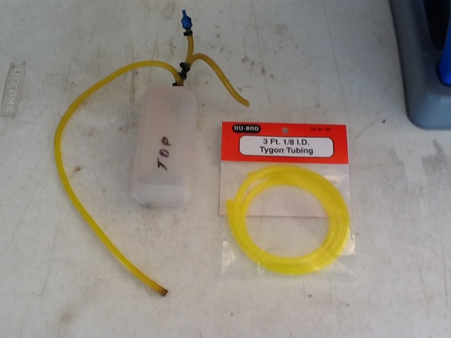
Next will be a rebuild of the fuel tank. I noticed that the clunk line had hardened which indicates that the fuel line is of poor quality. I did some research and Du Bro is supposed to be good quality.
I read a lot of comments about the varied quality of the yellow colored fuel line supposedly being made of Tygon. There is a lot of poor quality stuff out there so I’m sticking with brand name only from here on out.
1/30/2012 – Got the Extra back in flying condition. If the winds don’t come back this weekend I hope to do a re-maiden.

2/11/2012 – Flew three flights in between the rain today. The engine ran strong and the plane flew great. I’m so glad to be able to fly the Extra again!

7/23/2012 – The Extra is still flying strong. Ready to switch over to Red Line Synthetic 40-1 oil mix. Also, the tail wheel bracket at the wheel attachment fatigued and gave way. After a couple of hundred flights I’m not too surprised. Ordered a new tail wheel assembly from Aeroworks for abount $12.00.
9/3/2012 – Had a strange ignition problem. Could not get a spark even after trying a different ignition. Checked for voltage going in and out of the ignition and this was fine. Last piece was the Hall Sensor. With no moving parts what could go wrong with it? But sure enough a replacement solved the problem.

01/01/2013 – The DLE-20 engine developed a knock so I sent it in for service. Repair is on hold waiting for parts.
01/26/2013 – For some reason I received a brand new in the box DLE20 from Hobby Services. Installed the new engine and flew it this morning just before the rain came in. Got some nice pictures of it before the re-maiden.

View slide show here: http://www.flickr.com//photos/90706694@N05/sets/72157632619000532/show/
1/27/2013 – As a testament to the old adage “you get what you pay for” I thought about the years and years of enjoyment I’ve had from this one airplane. It’s withstood some abuse and some non- planned contact with the ground, several airframe repairs and an engine upgrade and after 4 years it still flies as nicely as the first flight.
Here’s a break down of the incidents over the years:
- Runaway at full throttle into a ditch – ripped out landing gear, minor fuselage repair
- Upgraded engine from .75 glow to 20cc gas
- Stalled on low and slow approach – left wing tip repair and minor fuselage repair
- Rudder servo replaced – had quite a bit of gear train slop
- Tail wheel replaced – wheel assembly wore out
- Dead stick landing stall while trying to get back to the runway – replaced the landing gear, cowl, engine mount and minor fuselage repair
- Replaced ignition sensor
- New 20cc engine
6/3/2014 – Discovered at my new flying club that four of us have the Aeroworks Extra 260 in the red with black checker scheme in all of the available sizes! My little 260 is on the far left.

8/14/2016 – Well it’s been over two years now since I took the little AW 260 out for a spin and as I was preparing for it’s day in the sun I found that the stock fuel tank had split after only 8 years!

I’ve ordered a replacement Fourtitude V2 8oz tank and hope to get the 260 up in the air next weekend.


[…] Aeroworks Extra 260 Build Log Posted by: electricdan | December 25, 2008 […]
with the engine 75 is ax hover ?
Yes, it hovers just fine with the .75AX and has plenty of pull out power.
Ok !
Danny,
With the new OS 95AX available would you recommend it or stick with the OA 75AX
The plane has more then enough power with the .75 to perform IMAC and full blown 3-D.
Aeroworks even said that the .75 is more then enough engine for this plane.
Dan,
I just completed my build and pretty much built it with the same equipment that you used. The aircraft is very nose heavy. In your build comments you stated that you added an ounce of ballast at the rear and that you may move the battery aft. What is the final configuration? What did you use for ballast and how/where did you fasten it? Any other information you could share would be greatly appreciated.
Jack
Jack,
I used an ounce of the flat lead weights you find at a hobby store. I fastened them to the top of the tail wheel using two plastic ties.
After about 50 flights so far, I’ve had no problems with the weights, so I just left it there.
With the .75AX and additional 1oz. of tail weight. What did the final all up weight end up being?
Matt, I don’t have the means to weigh the plane.
Dan, I have just received an Aero-Works .60-.90 Extra 260 QB as in your Build Log. I would also like to use the O.S. .75 AX engine, but mount it horizontally on side using a Pitts style muffler. This would cause the needle valve extension to have to exit the top of the cowl at an awkward position.
Your response to this installation via e-mail would be greatly appreciated. Thank you.
The needle extension can be a simple piece of control rod. When you need to take off the cowl simply unscrew the need valve and remove it.
Hope this helps.
Thanks for the comment.
Dan, I took your advice concerning access to the needle valve and it turned out great. I also noticed that the extension rod could be removed by rotating the needle valve so that the set-screw was towards the front of the airplane, thereby leaving the needle in place, if so desired.
Thanks very much for passing this information on to me.
Great Video! I’ve been looking at the Extra & Edge for a while now. I’ve seen the Extra & Sukhoi fly at my field, but not like in your video. The engine/prop combo appears to be on the money, and also fairly inexpensive. I’ll bet it will do a knife-edge loop easily.
Thanks for the comment Allen. This is one of my favorite planes to fly. Simple and reliable OS 2- stroke.
Why did you choose the JR 921 RXR over the AR7000?
No preference, I just had the 921. With the new capabilities of the AR7000 with flight log capability, either is a good choice.
Your build log and photos are Better than the manuel. It showed me how to bolt the wing, and use the cotter pins as well. There was NOTHING about this in the manuel. Great job. I am kind of a newbie and now very confident i can finish this model
Thanks
Thanks for the comment. I’m glad the build log was helpful for you.
Good luck with the maiden.
Dan, have you tried to hover this plane yet? I’m curious since you’re using a 75. Also, what kind of RPMs are you running full throttle on the deck with that prop?
Thanks,
Allen
Allen,
It’ll hover, but not that good. I need a larger diameter prop which really means I need a good size four-stroke.
My setup fly’s IMAC really well, not so much 3-D.
I havn’t tach’ed it yet. I’ll try to get a reading the next time I fly her.
Hope this helps.
Hi Dan, Bob Thomas from the club. I just bought the 260 extra and plan to use the OS 75 ax from a deceased Pulse xt. Do you still have the plane and any long term undates? Do you wish you had gone with a Saito? I just built this exact plane with 50cc DA, very cool as I have never flown anything like this But my back does not like to drag it more then once a week. My goal is really pattern to get better with warbirds and some day jets. Nice review, later.
Hi Bob,
Plane is still flying. The .75 with a 14 x 6 APC is a really good fit.
I’m not a 3D’er but for sport flying, Pattern or IMAC sequences it works very well.
I don’t see a 4-stoke advantage for sport flying this plane.
See ya later.
For anyone who happens across this build log, I’ll add my 2 cents worth. This is my 2nd Aeroworks kit, the first being their 1/3 extra 260. I decided to get a 2nd gas but smaller and because the larger aeroworks kit was so nice, went with them again. This kit didn’t disappoint and the author’s experiences match mine. I started with the DLE (didn’t convert) but DID notice one defect he didn’t mention. Pay VERY close attention to the pull-pull hardware supplied. In my kit, 2 of the clevises were far too lose on the bolts and i could actually pull them straight off after screwing them on. Other than that Aeroworks value for the price you pay is absolutely outstanding.
I’m looking to buy this plane. I would prefer to use the gas 20 DLE, tired of the glow engines, but still not sure. I’m a little worried about vibration . Do you have a preference over the os 75 or gas 20 DLE.
Craig
You won’t be disappointed.
I have a Satios 91 w/a 14 x 6 . Will this engine work with this model?
Perfect combination.
y would like to know if the extra 300 .60-.90 from aeroworks with dle-20 if have a good power to mantaine a safety hover ,its possible to hover with this engine? thanks,jerry
Jerry,
You shouldn’t have a problem hovering the 300 with a DLE-20.
Good luck with your conversion, let me know how it turns out.
Danny
Great build. I happened upon this while surfin’ the net looking for a home for a spare DLE-20 that I have. Overall, how do you like the combo?
Jason,
It’s a great combo and you won’t be disappointed. Let me know how your’s turns out.
Danny
Thanks danny
what do you use to charge A123 battery , how many flight do you get with one full charge ?
I use the Cellpro Multi4. http://www.usastore.revolectrix.com/Products_2/Cellpro-Multi4_3
After a 4 flight day, when I recharge the battery I put in around 500 mAh. Not to bad running the receiver and ignition off of a single battery. Prior to the conversion, on glow power, I was putting about 350 mAh back in after 4 flights.
http://www.rclipos.com/A123_Packs.htm. Does the 2300 mah capacity battery would need any standard connector to go into spectrum receiver?
For the battery shown at RC Lipos, you’ll need to either make an adapter going from Deans to a standard connector, or replace the standard connector on your switch to a deans or ask RC Lipo if they can add a standard connector like the batteries from this place: http://www.3epower.com/servlet/the-230/1-pcs-A123-Racing/Detail
thanks much buddy, I am totally following your article for my build and its a great effort from you. Very appreciative. So is this a legit place to buy batterys as well ? : http://www.3epower.com/servlet/the-230/1-pcs-A123-Racing/Detail
Thanks for the comments, I’m glad you are finding some useful information.
I have made several purchases from 3epower (Battery R’ US) and have had no issues at all.
Dan, so you standrad connector from battery needs to go into the switch and I can charge battery from switch ? ( what AMP ? ) . JST-XH balance connector ( on the battery )needs to be pluged each time for balance charging ?? Is there any benifit of using “deans plug” from battery for connection to switch ( may be for high AMP charge? )
rds
Kaka
I’ve never charged an A123 using the standard connector, I always use the balance tap. My charger won’t work with the standard connector, it needs to identify the number of cells for safe charging.
A Deans plug would only be necessary for the higher AMP draw as you’ve noted.
Dan, I am going to order same charger http://www.usastore.revolectrix.com/Products_2/Cellpro-Multi4_3 or 4 s Gold from site, does it needs to be connected to the JST-XH balance connector on the A123 ( has 3 wire on it) or even if connected to the “JR” connector on the battery ( 2 wire) the charger will do the balance charging ??
what else I need to order with the charger as I have those A123 batteries from 3epower ( 3 connections ) and MPI switch on the plane. sorry a long list but I need help 🙂 . regards
Kaka
The only way to charge is with the JST-XH adapter:
http://www.usastore.revolectrix.com/Products_2/Cellpro-4s-Charge-Adapters_2/Cellpro-JST-PA-4s-Charger-to-Great-Planes-JST-XH-or-Kokam-JST-EH-HR-Adapter
Have you tried the Jtec wrap around pitts muffler on the DLE20 with this air frame? the engine box is not alowing me to use the Jtec and will have to put stock muffler on. I was wondering if anyone else has tried this combo and what results they had.
Thanks Eric
Nope sorry, didn’t try a Pitts muffler.
Putting on pitts muffler. Had to add hardwood block to inside motor box front, then took off the front edge of motor box to allow the jtec pits to fit. Also put motor approx 4 7/8 out from motor box.
Sounds like a bit of extra work. Just wondering what the benefits might be using the Pitts style muffler?
Just want to say your article is as astounding. The clearness for your put up is just excellent and i could suppose you’re a professional on
this subject. Fine together with your permission allow me to
seize your feed to stay updated with coming near
near post. Thanks 1,000,000 and please keep up the
rewarding work.
Thank you Chang. I’m sorry I missed your comment.
Just picked up a used Extra 260 with the dle 20 conversion. I have yet tomput it in the air. Does yours want to tip stall if you yank full elevator?
Yes it does, but you’ll have a lot of fun with this combination.
Hi. great explanation. I have a question. I have got saito 125 and I want to put it on this plane. Do you think it is ok. Thanks.
Hi Dan,
I’m about to start assembling a AW Extra 300 that I had stored for some time. It looks like it has the same dimensions as your Extra 260. I’m planning on using an OS 120AX on this one and looking to the motor box, I believe it’s best to put it inverted like your DLE20. Do you think there’s enough room to put a wrap around muffler or should I stick to a side mounted muffler like yours? Thanks for your help.
Mario.